
My Model Flying Club - South Cheshire Radio Control Society - as a challenge for its Fun Fly day has decided to hold a BMFA Dart Challenge. Turn up on the day and (weather permitting), 2 flights and the flyer with the best cumulative score (flight time) will win.
I decided that I would document how to build a Dart with a short photo essay and perhaps a few tweaks here and there to help would be builders.
The kits are available from the BMFA https://bmfa.org/
Its quickest just to phone them and pay using a debit/credit card
British Model Flying Association
Chacksfield House
31 St Andrews Road
Leicester
LE2 8RE
Tel: (+44) 116 2440028
Fax: (+44) 116 2440645
Email: admin@bmfa.org
Due to the amount of packing required, its worthwhile rounding up a few friends and placing a bulk order to keep the shipping costs at a sensible price.
So what do you get for £2.00
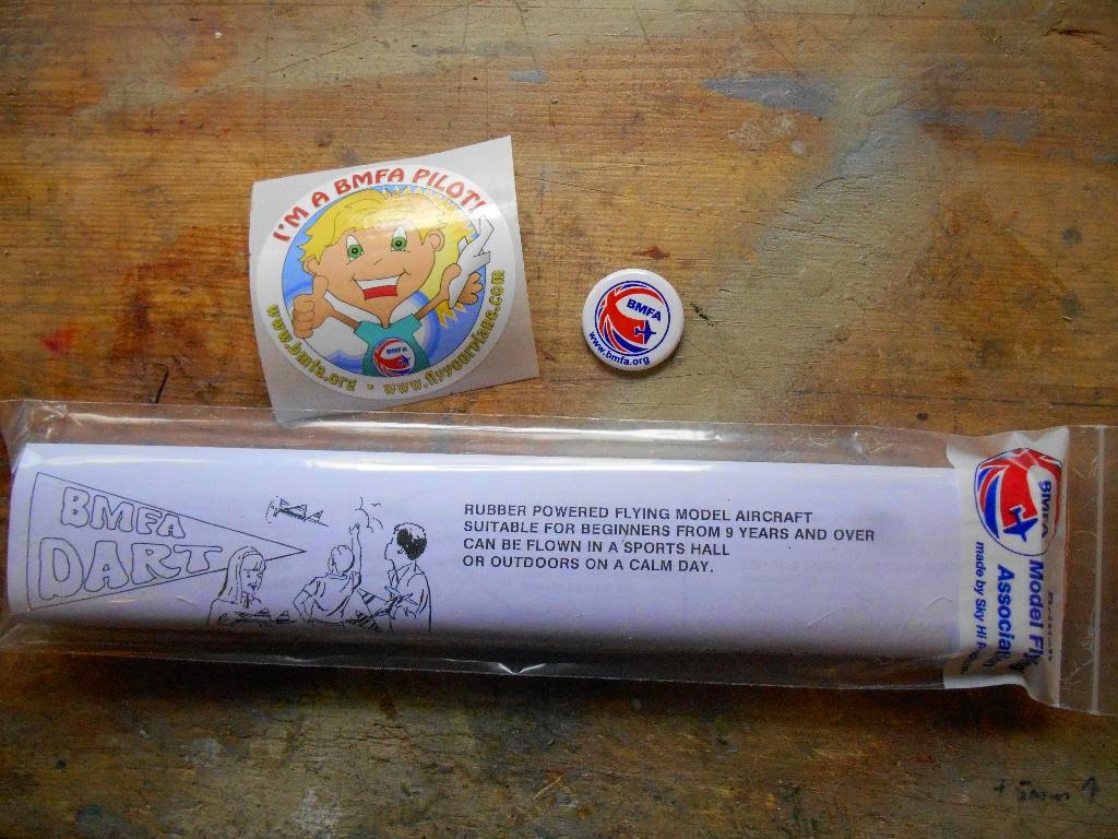

Unpack the kit being careful not to break anything. The kit comprises of a plan, instructions, propeller assembly, a motor stick - pre cut, some lengths of 1/8" x 1/16" balsa and a length of rubber to make up a motor..
Have a look at your balsa, try and identify the pieces that feel the stiffest or are a little heavier - put these aside, we will use them for the wing.


The first thing to do is slit the plan on the A-A line as shown. The balsa airframe is glued to the plan - this provides the flying surface covering and this bit is under the fuselage while you are assembling the fin.

Mark the motor stick where it crosses line A-A and apply a little PVA glue to the back, making sure it is well smeared - you only need a tiny amount of glue, more will come off on your fingers than is left behind which should only feel slightly tacky.

Pin the motor stick down (the right way up), you need to keep all the parts secure while the glue dries.

The next task is to cut the wood for the fin, simply lay the part over the plan and where it crosses, mark with a scalpel. Don't try and cut through, just mark it by running the blade over where the join will be.

Like this... take the part to a spare part of the board and SLICE the wood in a single cut, don't force the blade through or you will crush the wood

Glue the piece into place, put a blob of glue at the end plus a couple of very small blobs along the underside and smear it down the length. Very little glue is required. Put the part down on the plan and pin into place making sure the joint with the motor stick is sound. Repeat for the next piece

You will need to cut and add a little balsa gusset into the joint at the top of the fin. These are very small and tricky to get right, but persevere, it should be a snug fit requiring very little glue.

Although not shown on the plan, its worthwhile adding an additional gusset at the base of the fin, front and rear, they add a lot of strength for minimal additional weight.

When the glue has dried, use the scalpel to cut all around the fin and lower fuselage up to line A-A. Don't cut off the little triangle of paper at the top of the fin, this gets folded over and reinforces the joint

Cutting along the base of the motor tick to A-A

Fold the little triangle of paper over and glue to the top of the fin

You can now remove the fin and motor stick from the board admire your handiwork..

The wing is built next. From the harder/stiffer wood you put aside above, try and match them in pairs and use the hardest/heaviest wood for the leading (front) edge of the wing. Follow exactly the same procedure that you used to build the fin EXCEPT

Don't glue the joint in the middle of the wing. The spars and cross members are glued to the paper though, just don't glue the central joints yet.

There is one additional cross member on each half of the wing, this does need to be glued into place.

The tailplane is built in the same way. This is a simple triangle shape , don't forget to add the gussets to help support the joints. Definitely the most fiddly task.

The joint at the tailplane tip

When the glue is dry, cut around the wing and tailplane as you did for the fin, its coming along nicely now.

Here is where I differed from the supplied instructions. Dihedral - the wing tips need to be tilted upwards - provides stability to the model. My method of doing this follows fairly normal practice. Cut two strips of wood 2.5" long. These will be used to support the wingtips.

Put glue (fairly liberally) around the two joints at the front and rear of the centre of the wing

Lay out some cling film and pin the centre cross member absolutely flat down, through the film onto the board.

Prop up each wing tip with one of the spacers that you cut, one at each side. Let the glue dry thoroughly - this may take a couple of hours. I also ran a little cyano acrylate (superglue) on top of the paper at each joint and let it soak through. This really needs to set solid before you disturb it.

While the glue is drying and if you feel so inclined, we can start work on improving the propeller assembly. This is a fairly simple shaft drive with the metal arm locating in a spiral notch at the front of the propeller. The problem with this is that it makes a very poor freewheel, when the motor drive stops (runs out of turns), you need a decent free wheel to make the best of the glide. This is my solution to the problem.
First, carefully remove the old shaft, either cut it away or bend the clutch straight and slide the shaft out. Throw it away.

Using a piece of 20swg piano wire, solder a 10BA nut and washer about 30mm from one end. Make sure that the shaft is cleansed with a bit of sandpaper beforehand - to remove any oil that will prevent the solder from flowing. Use as little solder as possible, we are only trying to locate the nut and stop it from moving

Push the new shaft through the propeller and bend the end over at 90 degrees making sure that there is at least at 3-4mm gap in font of and between the propeller and the nut/washer that you have just soldered into place. The propeller should spin freely

You now need to modify the lock assembly on the propeller to retain the arm. This involves cutting and filing a notch or small slot into the propeller for the drive arm to sit into when its on load. Click on the photo for a large image

Push the shaft through the front bearing. It would be better if you also add a small plastic bead, that sits between the nut and the bearing/shaft. Something I forgot to do.
A loop is then bent into the end of the shaft. This has to be quite tight, but leave the open end like the photo. This will help prevent the motor from creeping off the shaft when its fully wound. You can see why the loop has to be tight - any larger and it would foul the housing assembly.

Glue the tailplane into position making sure that it is at 90 degrees to the fin - i.e. horizontal. Allow the glue to dry

Mark on the front of the motor stick the position of the leading edge of the wing. This should be 1.25" back from the prop shaft bearing,

By now, the wing should be dry. Remove the supports and check that the wing is indeed stiff and will support its own weight. Glue the central cross member to the fuselage, pin it into place and check by eye that the dihedral is equal on both sides.

Nearly finished, just need to add the rear motor peg.

The instructions suggest that a pin is used as the rear peg. I chose to bend this from 20swg piano wire. It gives a larger contact area for the glue and also is slightly larger diameter and that will halp prevent the rubber from being cut by the metal.

Use a pin to make a hole and simply glue the rear peg into place.
That's about it. Enjoy
No comments:
Post a Comment