G-AELO is the target aircraft that I am going to try and replicate,
(image Wikipedia)
I have simply scaled down the original CAD drawing I produced and I am using this as the primary source for the airframe structural layout. As the CAD drawing is currently incomplete, it is likely that I will have to rework substantial parts of the model. Hopefully not too much rework though.
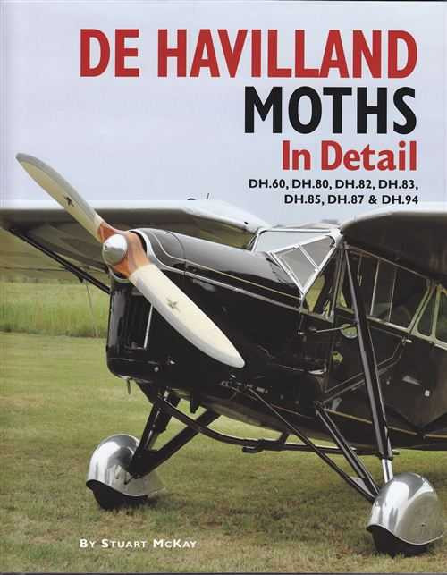
G-AELO is also one of the featured aircraft in the book "De Havilland Moths in Detail" by Stuart McKay.
This is the plan that I am currently working to. It's traditional Stick and Tissue construction but with micro RC gear fitted. The Scale Maestro Danny Fenton is also giving me lots of guidance and for that I am exceedingly grateful.
The plan was tile printed from PDF and the A4 sheets taped up then trimmed. A very low cost way of producing a plan
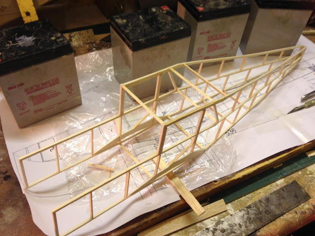
A couple of evenings in the shed and one side is almost completed. The cling film is to protect the airframe - not the plan.
The second side is built directly on top of this side (separated by cling film) and then joined together using cross members with measurements taken directly from the plan. That curved top elevation will be fun to achieve.
The fuselage sideas are jigged upright and then a few selected spacers added. The whole lot is then weighed down carefully and the glue allowed to dry thoroughly. The taper behind the wing is straight and very simple to achieve. The taper in front of the wing is curved and different top and bottom and far more challenging.
Very fragile in this state, I cant imagine how many spacers I have to secure. Glue is weight and is kept to a minimum, sometimes a little more is required.
The front fuselage spacers added and work started on the fin.
I used a laser dye transfer method. I am trying to get the appearance of a scale structure. The method is quite simple, laser print the shape with ribs etc. Flip the print face down on the balsa with the grain running in the correct direction and then rub a little cellulose thinners through and the image is magically transferred onto the wood.
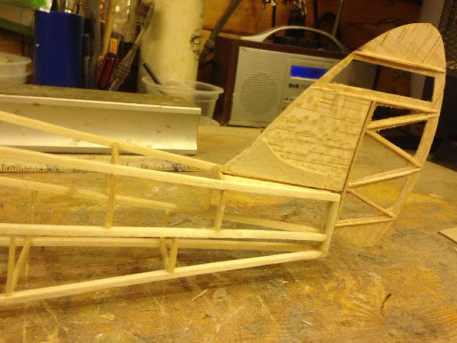
This has a 1/32 balsa core hollowed out around the 1/32 doublers in the fin area then a significant amount of wood is removed from the rudder, leaving mainly an outline and the 1/32 square ribs. The whole lot is then sanded down to a streamline.
It sits in the top of the fuselage with the small tongue located in a slot in a 1/32 fill sheet. Weight of the fin and rudder is 1.44gms
The nose block was manufactured from 1/2" very light sheet balsa. A suitable sized washer - the same diameter as the spinner was tacked into place and gave me something to sand to.
Its not quite the correct shape yet, but its not a million miles out either
And this is what it looks like. The 3 curved upper front deck formers are slightly too high and need to be reduced by a couple of mm.
The cockpit was fabricated and installed before the fuselage could be covered.
I was really quite pleased with that console as a first attempt
Cant claim any credit for the pilot. He is actually slightly too small in scale and I did have to provide legs and paint him (now known as Cedric).
And installed..
Wing construction is fairly traditional for indoor models, comprising of wing ribs created by wrapping a preformed (sliced strip) for the top and bottom over internal spars. I a not entirely happy with this method of construction. While it is undoubtedly very light (the wing panels weighed 8 grams each), I found it rather too fragile for my ham fistedness.
Ailerons were built with the wing then separated when ready for covering then hinging
The flight radio gear was procured from Micron UK, comprising of a micro Rx and servos and a park-fly motor, gearbox and prop.
Carbon push-rods used for the aileron linkages out to traditional bell-cranks. Horns fabricated from 1/32 plywood.
I found covering very difficult. Any construction errors were magnified by the resulting creases and it took many attempts to get it to a state that I was half happy with.
Windows frames cut from a very thin baking tray and glazing from the base of a cake tray.
Interplane struts are located using a bent pin through a small loop in the correct place
Lettering and logos were produced in Photoshop then transferred back into CAD to make sure that the size was correct then printed onto transfer paper then finally sprayed with car lacquer to make them waterproof, before they ere placed in water to separate them from the backing
When finally finished, it looked like this
A very interesting project. I am not entirely happy with the wings as they have bowed slightly and may redo them but I think its not a bad representation of the original.

.jpg)


No comments:
Post a Comment