Showing posts with label Scale. Show all posts

Monday, 3 April 2017

DH87B for Indoor Scale

I have been asked to take part in the indoor Scale Nationals at the end of March 2017. Probably being rather overambitious but I have taken up the challenge and will try and build a 1/14 scale DH 87B Hornet Moth.

G-AELO is the target aircraft that I am going to try and replicate,

(image Wikipedia)

I started work on the plans in 2015 - it was originally intended as a Free Flight Scale model at 1/12 scale (31" span) - something I may attempt to start and complete again in the future.

I have simply scaled down the original CAD drawing I produced and I am using this as the primary source for the airframe structural layout. As the CAD drawing is currently incomplete, it is likely that I will have to rework substantial parts of the model. Hopefully not too much rework though.

G-AELO is also one of the featured aircraft in the book "De Havilland Moths in Detail" by Stuart McKay.
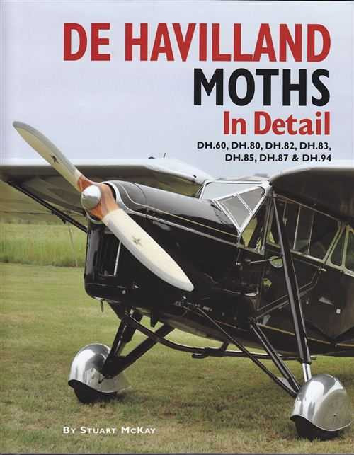


This will simplify getting the supporting documentation needed for the competition. By the way, the book is an excellent read, a great deal of information provided in a manner that is very interesting with some superb photography to support the text.  Makes you feel part of the story. Highly recommended.

This is the plan that I am currently working to. It's traditional Stick and Tissue construction but with micro RC gear fitted. The Scale Maestro Danny Fenton is also giving me lots of guidance and for that I am exceedingly grateful.


The plan was tile printed from PDF and the A4 sheets taped up then trimmed. A very low cost way of producing a plan


There is not much actual build information on the plan, its really just a parts placement plan so ideas will be tried (and many rejected) as the model is being built. I'll also be trying out some new ideas as well


A couple of evenings in the shed and one side is almost completed. The cling film is to protect the airframe - not the plan.

The second side is built directly on top of this side (separated by cling film) and then joined together using cross members with measurements taken directly from the plan. That curved top elevation will be fun to achieve.


The fuselage sideas are jigged upright and then a few selected spacers added. The whole lot is then weighed down carefully and the glue allowed to dry thoroughly. The taper behind the wing is straight and very simple to achieve. The taper in front of the wing is curved and different top and bottom and far more challenging.


Very fragile in this state, I cant imagine how many spacers I have to secure. Glue is weight and is kept to a minimum, sometimes a little more is required.

The front fuselage spacers added and work started on the fin.

I used a laser dye transfer method. I am trying to get the appearance of a scale structure. The method is quite simple, laser print the shape with ribs etc. Flip the print face down on the balsa with the grain running in the correct direction and then rub a little cellulose thinners through and the image is magically transferred onto the wood.


This has a 1/32 balsa core hollowed out around the 1/32 doublers in the fin area then a significant amount of wood is removed from the rudder, leaving mainly an outline and the 1/32 square ribs. The whole lot is then sanded down to a streamline.

It sits in the top of the fuselage with the small tongue located in a slot in a 1/32 fill sheet. Weight of the fin and rudder is 1.44gms


The nose block was manufactured from 1/2" very light sheet balsa. A suitable sized washer - the same diameter as the spinner was tacked into place and gave me something to sand to.


Its not quite the correct shape yet, but its not a million miles out either


And this is what it looks like. The 3 curved upper front deck formers are slightly too high and need to be reduced by a couple of mm.

The cockpit was fabricated and installed before the fuselage could be covered.


I was really quite pleased with that console as a first attempt


Cant claim any credit for the pilot. He is actually slightly too small in scale and I did have to provide legs and paint him (now known as Cedric).

And installed..

Wing construction is fairly traditional for indoor models, comprising of wing ribs created by wrapping a preformed (sliced strip) for the top and bottom over internal spars. I a not entirely happy with this method of construction. While it is undoubtedly very light (the wing panels weighed 8 grams each), I found it rather too fragile for my ham fistedness.

Ailerons were built with the wing then separated when ready for covering then hinging


A sort of bare bones shot.


The flight radio gear was procured from Micron UK, comprising of a micro Rx and servos and a park-fly motor, gearbox and prop.


Carbon push-rods used for the aileron linkages out to traditional bell-cranks. Horns fabricated from 1/32 plywood.

I found covering very difficult. Any construction errors were magnified by the resulting creases and it took many attempts to get it to a state that I was half happy with.


 The model was covered in red and silver Esaki Jap tissue. The orange roof panels were from Orange cellophane from a brand of Jaffa Cakes.


Windows frames cut from a very thin baking tray and glazing from the base of a cake tray.


Tailplane and rudder


Interplane struts are located using a bent pin through a small loop in the correct place


Lettering and logos were produced in Photoshop then transferred back into CAD to make sure that the size was correct then printed onto transfer paper then finally sprayed with car lacquer to make them waterproof, before they ere placed in water to separate them from the backing

When finally finished, it looked like this


A very interesting project. I am not entirely happy with the wings as they have bowed slightly and may redo them but I think its not a bad representation of the original.

Monday, 9 January 2017

DHC-1 Chipmunk - wing

After about a 18 month break, I have restarted work on the Chipmunk. The Fuselage has been parked for the time being and I have started work on the wings. Nothing too challenging at the moment, it is simply a case or reigniting my enthusiasm, getting a bit of progress and hopefully, I'll now see this through to completion.

As before, it will have to fit in with whatever else is happening in the Shed, but now I have got the irritating bits of the design out of my system (it's scale accuracy), I feel much happier and I'll now try and get this completed and with a moderate amount of scale detail. Like all large projects and eating elephants, its best to approach the task, one bite at a time.


The parts kit is almost complete (centre rib and 2 1/16 ply brace/doubler ribs not present - but that's not a problem) although the balsa wing rib wood is rather hard and prone to splitting. Still quite usable but I am not sure how it will survive a hard arrival.


Lots of clamps used to make sure the joints are nice and tight. The number of braces in the centre are in my opinion rather excessive but that is what we are stuck with. The wing certainly wont fold in flight. It was actually far more difficult to get the two panels to align correctly surprisingly. It took me 3 attempts to get it to where I am happy with it.


 Progress so far has been slow but the upper wing sheeting has been added. I can how start work on the aileron push-rods and the undercarriage. A bit of belt and braces while work progresses on the overly delicate Hornet Moth


I was never happy with the original method of retaining the torsion bar undercarriage legs which used tinplate straps binding the legs and then screwed to a hardwood block. The centre section is so over engineered - this looks like a potential weak point.

My approach has been to implement much larger beech blocks and cut a deep channel. Aluminium plate saddle clamps will hold the leg in place without risking damaging the wing skins  which sit below the torsion bar.


The anti twist stop will use a metal saddle clamp - bolted through the wing ribs


 Hobby King Oleo legs grafted onto the end of the torque rods. These are designed to be clamped. Its quite an easy task to drill out to 4mm to fit (interference) with the 8swg (4.1mm) diameter rod.

M3 hole drilled and tapped all the way through and cap head screws used to clamp the legs in place. A small flat will be ground on the legs to prevent them twisting


The sprint tension is too tight. The spring needs to be reduced in tension so that the leg compresses by about 6mm with (guessing) about 1.5kg load on them. I don't want to soften the spring, simply reduce the preload - the easiest approach is to incrementally reduce the spring length.

Sunday, 11 December 2016

Fairey Delta 2 - PSS (1)

I am being 'encouraged' to have a go at building a Powered Scale Soarer - a model based on a normally powered prototype, but primarily designed for flying as a Slope Soarer using lift generated by the upward movement of the air as it rises over a hill.

I didn't do a lot of research. It appeared that many of the PSS models were scale models of Jet Aircraft and I fancied a cold war era aircraft. I actually knew nothing about the Fairey Delta 2 - it just looked right - and I decided that would be the design I will model.

Gordon Whitehead kindly provided me with a short article detailing the history of the aircraft and I have reproduced it as a short PDF document that can be downloaded


Fairey Delta 2


I am designing at 1/6 scale. This gives a model with a modest wingspan of 1.36m but with a fuselage length of 2.62m - with a very pointy nose..


Fairey Delta 2 Dimensions

Specifications (Fairey Delta 2) - from Wikipedia

Length: 51 ft 7½ in (15.74 m)

Wingspan: 26 ft 10 in (8.18 m)
Height: 11 ft 0 in (3.35 m)
Wing area: 360 ft2 (33.44 m2)
Empty weight: 11,000 lb (4990 kg)
Gross weight: 13,884 lb (6298 kg)

1/6 scale


Wingspan 1.36m
Length 2.62m

Length/Span Ratio 1.92:1

Working with a hybrid of design tools, DevFus for the Fuselage and Profili for the wing and then consolidated with Draftsight 2017 - this is still Work in Progress.

Design is obviously simplified as there is  no engine and undercarriage..

Wing section is based upon the NACA M4, but with the camber reduced to give a semi symmetrical front part of the profile but still retaining the slight reflex.   

It should be OK for this model. Its quite thin at just over 6 percent thickness, but the root chord is  huge by my standards at 915mm!

The wing section will taper linearly and transform to a simple NACA0008 at the wing tip. With a tip chord of only 98mm, the thickness at the wing tip is only 8mm thick. Getting this built and maintaining strength to handle slope side landings will be tricky.

Output from DevFus looked like this:

considering 3mm ply formers, spruce longerons and covered in a mix of 3mm Depron and Balsa.

The wing outer panels will plug into the centre section with the wing split at an angle from the side of the dummy air intakes to the fuselage side. I envisage that wing construction will be carbon composite spars and joiner tubes, balsa sheeted leading edge and Depron sheeting behind the main spar. Something along those lines anyway.. :)

The plan is at this stage. The Depron Balsa mix has not been decided but the keel area will be planked in 3mm spruce to provide a little resilience for those rocky landings.


That is just about where I am up to.

More to come..

Monday, 18 May 2015

Dennis Bryant DHC-1 Chipmunk - Back end

This is my contribution to the RCM&E Mass Build for the Dennis Bryant Chipmunk. Built from the Traplet plan and part kit from about 40 years ago, the plan isn't quite as true to scale as I would have liked.

My build blog is here, but I thought I would put an occasional posting here as well..

This past weekend, I have been working on the tailplane and Rudder. Danny Fenton - a true scale master - has been guiding us through some of the steps needed to produce a realistic looking aeroplane. This is my first attempt at producing anything scale like.

Because all the linkages are hidden, assembly is really quite complex, so a couple of shots to show where I am.


The two linkages - upper rudder, lower elevator are buried in the fuselage under the tailplane and fin
The clevis connects to the tiller arm for the tailwheel, I need to attach the rudder tiller to the same rod.


Broadly, I have used a brass terminal screw block to clamp the rudder tiller. This has a short brass plate with a hole drilled in it The tube supports the axle and arm that drops into a hidden slot in the rudder. The pin protrudes down through the plate and has a soldered washer to retain it.


The tube is now supported by a small strip of lite ply. One problem is that the arms rocks very slightly as the tiller moves in an arc as it is turned from left to right. It moves about 0.5 mm. This is because the tiller lengths for the tailwheel and the rudder are slightly different. However, as you can see, the axle is a sloppy fit in the tube. I am really hoping that I can get away with it...


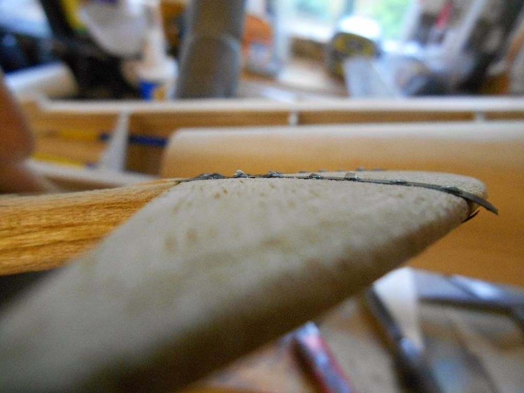
Now, following Danny's instructions, its time to add some rivets. I have added a couple of strips of vinyl tape to simulate a joint in the metal sub structure and then using small drops of PVA applied with a syringe, I have added a few 'rivets'.


The riveter is a cheap syringe with a little glue and lots of air. Danny uses a little dispending bottle, but my thought was that once I get the pressure right to get a slow but constant flow rate, it should be simple to quickly move from dot to dot adding the rivets. It seemed to work OK.


You can see from this shot they just stand proud..


 When done and allowed to harden ( for a good coupe of hours). the rudder was covered in White Solartex carefully avoiding the rivets as they would flatten under the heat. (in fact I lost 2 in the process)


The next task is to weigh up what order to assemble the rear components, this is far more complex that it looks. I also have to add a carved tailpiece to finish off the rear fuselage. This will totally embed the elevator linkage. However, I cant do any of that until the tailplane and fin detail has been added, so rib tapes and stitching next


This is going to be a long slow build..