Showing posts with label UKCAA. Show all posts

Wednesday, 1 June 2016

Mystic 40

This is Hanno Prettner's 1993 World Championship model - scaled down for a piped 40 or possibly a 60 sized 4 stroke,

It results in a model of about 56" span and hopefully quite light.


 The design was actually pulled together using DevFus for the Fuselage and Profili for the wing. This enabled me to get the shape of the formers exactly right without needing to guess or manually interpolate.


A very slender fuselage and surprisingly deep. Its not really obvious from the until the size of the fin and wing is considered.

A detailed build blog exists on the Model Flying Forum  which covers many of the constructional aspects of this model and will not be repeat here

The output from Profili and DevFus were combined into a single file and edited using DraftSight. The parts were transferred to DXF and sent Dylan at LaserCraft for laser cutting - Liteply and Birch Ply wing ribs and fuselage formers

So rather than repeat the build blog, just a few progress photos here:


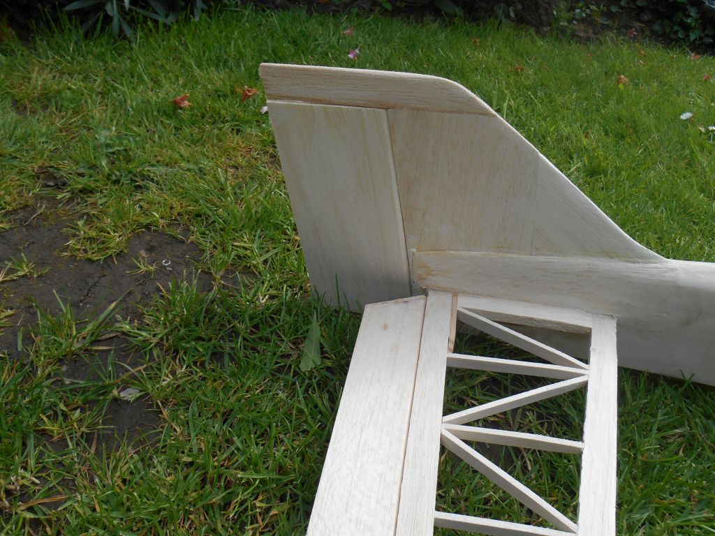
Tailplane construction is quite simple, the trick is to select good quality light wood. Elevator hinges using Kevlar cloth which is what I tend to do nowadays


The fuel tank area and Firewall are assembled as a crutch and the fuselage built up around it


Fuselage construction is quite straightforward


Upper decking is 1/16" balsa sheet


Wing construction is traditional. Building tabs used to make sure the wing stays flat

Retracts are HK copies of e-Flite and a cheap MG996 servo used as the retract servo.


And a video of them working


Leading edge sheeting added and a dry fit of the model - looking OK :)


Next bits were the tuned pipe tunnel, ailerons wing tips and rudder


 Wing tips hollowed using a dremel and sanding drum after the external shaped had been roughly carved and sanded to shape. A lot more wood than that came out.


The lower fuselage was crafted using lite ply formers and soft balsa sides


 Rudder laminated from 3mm balsa. The fin cap has a 3mm lite ply base to help keep it nice and straight and importantly, add a lot of strength. Balsa on its own is just too fragile


Ailerons laminated from 5mm balsa sheet over the Kevlar hinge. The ends are capped with 3mm lite ply to maintain nice crisp edges


 The Canopy came from an old defunct model that lost its life when an aileron linkage broke..


And so far, it looks like this.


Friday, 23 October 2015

Flair Meteor

I bought this 35 year old kit at a recent UKCAA event with strict instructions that it had be be built not stored. I remember the kit from a long time ago although I was (and still am) having problems dating it. Estimates are that it was produced from the late 1970's into the early 80's

The kit is a  fairly basic constructional specification, foam wing and a very distinctively shaped glass fibre fuselage. It's quite a small aeroplane - about 52" span and originally designed for a 40. The planned modern 46 will make it very fast flying.


 The original box was rather large and was cluttering up my workshop so this was a big incentive to get started. Additionally, I had spare moments available during the Glass Slipper build and the opportunity was too great to ignore it.


 The photo on the front - it looks very 1970ish


I was quite fortunate that the previous owner had bought some new foam wing cores. The rest of the materials were as original with some beautiful quality balsa - which was very dry.


One of the earlier owners had made a start - and a bit of a mess gluing the bulkhead in place. The surplus resin was removed with a Dremel and sanding drum and the former re-drilled to suit an engine mount that fitted my chosen power plant  - an SC46 from my recently departed Gangster 63. You can also see the ply shim added to provide a little right thrust.


 The engine has recently been serviced with new main bearings, has good compression and has so far been very reliable.


The engine mount held in place with cap head bolts and blind star nuts. The quality of the piano wire was excellent - black - high carbon steel - far better than the rubbish we get nowadays


The tailplane was fitted - it was very simple to align as there is no real option - the moulded slot simply fitted and then I added the full length elevator hinge blocks, using Kevlar cloth as the hinge material. The only critical part was getting it centred and also triangulated to the centre at the nose to make sure it wasn't skewed.


Likewise, the fin, rudder and rudder post simply slotted in and was almost guaranteed to be vertical. Slow setting epoxy was used to hold it all together. By modern standards, the rudder is quite small but I resisted the temptation to increase its size. (For the time being).


 The wings were glued together using Gorilla Glue  before 170gm fibre glass cloth was used as the bandage. Slots for  the U/C bearers were carefully cut and the blocks inserted and glued using Gorilla Glue.


The ailerons were cut out using a band saw with the wing jigged to make sure that the cuts were vertical. The middle piece was removed as this is where the hinge blocks will be fitted.


Sanded down ready for glassing


The wing retaining bolt platform is from the kit and comprises of a small length of TE stock and a plywood face. I have replaced the original 2 x M4 plastic bolts with a single M5 steel cap headed bolt


Min servos fitted into the wing and slightly recessed. This may cause some consternation, but the power output of these small servos is far higher than standard servos of the 1980's. 3kg/cm should be more than enough for a single aileron.


Once again, Gorilla Glue was used to assemble the ailerons, hinge blocks and wing. The ailerons and wing were capped with lite-ply  to keep a nice sharp edge.


Fitting the belly pan was the only real tricky part of the build. I eventually hand drew a symmetrical hour glass shaped waist  and carefully removed the excess on the bandsaw. I was either a very good judge or very lucky because very little additional fitting was required.


It took a couple of evenings to cover the model, A mix of film from different manufacturers was used - basically, what I had in stock.


I didn't bother with the outline canopy, I prefer its nakedness and raw elegance.


Underneath a different scheme was used - similar to that I used on the Concept. I hope this model lasts a bit longer.

The covering has also been sealed using SolarLac - it helps prevent fuel/oil ingress under the film and keeps it properly adhered. This is quite important around the Glass Fibre to film junctions. In my experience, film does adhere particularly well to Glass Fibre or resin.


AUW - Dry 2.35kg. About 200g less than suggested in the manufacturers instruction leaflet.

Additional parts I had to supply:

1. 3 x Wheels (2.25")
2. 10oz SLEC square fuel tank (Yellow)
3. 10x8 prop. I would normally fit an 11" prop but there isn't much ground clearance. Hopefully the 8" pitch will keep the revs (and noise) down.
4. Snakes' clevises, saddle clamps etc,
5. Servos - Futaba S148 for Ruder and Elevator and E-max E5363 for the ailerons
6. FrSky X6R Receiver with telemetry

Looking forward to seeing this fly.

Monday, 12 October 2015

Kwik Fli IV (5)

The Final Part...

Back on the cowl.

The engine has been temporarily fitted (and subsequently replaced with a SC61)

dscn1784.jpg

Hardwood blocks added to locate the cowl

dscn1785.jpg

Wrong sized spinner but currently it fits like this

dscn1786.jpg

Managed to chip the glass when trimming down to size but that has subsequently been redone
Its not too bad - weighs 80g.

The next job was to get the wing to fit.
The chord is 1.5" wider at the root than the standard Kwik Fli III wing. The 2 pager out of RCM&E doesn't actually say how to make the change. The root wing section is also somewhat different to the mk III as well so a certain amount of trial and error and sanding etc. to get the wing to fit at the same time at getting the wing level with the tailplane.

dscn1788.jpg

A thick ply wing plate has been fitted - using slow dry epoxy and the wing drilled for 2 M5 Nylon bolts. I then realised I cant measure.. and managed to displace one of the bolts by 5mm 

dscn1791.jpg

I am so cross with myself over that stupid error. Its not too noticeable with the wing fitted though.
This morning, I started fitted out for the radio gear. 3mm Lite ply plates on 10mm sq Pine runners and cross beams.

dscn1795.jpg

After the usual faffing around

dscn1796.jpg

The receiver was replaced with an X8R


dscn1805.jpg

So - this evening, the model assembled on the stand

dscn1806.jpg

And another one, I like it when they are like this...

However, I need to check the wing incidence

dscn1807.jpg

We already established that the tailplane is parallel with the datum. so put the phone on the tailplane and press the zero button

dscn1808.jpg

Put the phone onto the incidence measuring jig platform

dscn1811.jpg

0.4 degrees positive. The plan says for the MkIII it should be +0.5, so that is pretty close. Certainly close enough to risk flying it and then assess. To sanity check, reverse the jig. If the jig is accurate, the incidence should be exactly the same (it was).

dscn1812.jpg

It looks aligned as well. No obvious tail tilt

dscn1814.jpg

And it weighs this much so far. Probably looking at an AUW of 3Kg

The last couple of days have been spent adding detail, sanding down smooth and making a better job of the wing seat. Not much in the way of photos, so yesterday I decided to cover the model and now it looks like this.
dscn1815.jpg

and

dscn1816.jpg

A contrasting (and much simpler) colour scheme underneath

dscn1817.jpg

It's been Tangoed!

This morning I completed the installation of the Radio Gear, everything appear to work in the right direction but it will get final checks before its let loose.

Conventional (if very short) 8G torque legs have been bent up. 8G is about 4mm dia, however, the orifice in the top of the oleo is 5mm so the leg (about 15mm long) was padded out with a length of 0.5mm wall brass tube, hammered into place. The lower set screw location now located in a slot ground into the leg. It seems quite sturdy, time will tell

dscn1828.jpg

And that is the undercarriage done. Its actually not too heavy as the oleo and leg are manufactured from aluminium. Probably a bit more draggy though. If it doesn't work, its very easy to revert to conventional 8G piano wire legs. (Postscript - conventional legs have since been used, I couldn't get these to track consistently)

The cowl has been painted - KlassKote - thanks Andy Green - I painted (sprayed) it and the 'Magic' this morning (the white bits). Its a 2 pack epoxy paint and sets hard in about 6 hours on a warm day.
So now, with the undercarriage done, the cowl fitted and spinner fitted its ready for its maiden. I have a Taranis X8R receiver on order although currently it has a V8 fitted, I have decided to wait for the receiver that I want to use.

CG is a guess as no CG shown on the mods diagram. Currently set about 20mm in front of the main wheels.
The Canopy came from Vortex and sprayed Matt black on the inside after it was cut to fit. A small balsa former cut to the inside front and rear and this was used to glue it to the fuselage. The seam was sealed with Canopy Glue. Looks quite a neat installation.


dscn1822.jpg

and

dscn1823.jpg

and

dscn1824.jpg

It's Ready to Crash.. Aurora 60 next....
3 weeks and 3 days since the first part was cut.. It really is an easy build

Postscript - the model flies well, the cowl seems to have survived but the tailplane needs additional reinforcement. It failed doing a snap roll - folding slightly - causing down elevator and a rather rapid decent. All repairable but the tailplane now has a spruce spar extending about 150mm into each half.