Showing posts with label Slope Soarer. Show all posts

Tuesday, 29 December 2015

Glass Slipper (6)

Finishing it off..

The ailerons are rather thin in cross section and I was concerned that they would be susceptible to flutter. Rather than replace them, I simply trimmed the last 3mm and inserted spruce.


Hard points added and a razor saw used to separate the flap from the aileron.

There are 2 x 12.5mm thick wing ribs that are used to fair the fair the wing into the fuselage. These need to be carved and sanded to meet the complex double curve on the fuselage while still maintaining the correct facing angle to the wing. I almost got it right.

These ribs are faced with 1/16" ply which were glued into place before the carving started.


Alignment was carried out is 2 halves using my home made incidence jig to ensure that the wing was at +1.5 degrees
Elevator halves are braced with 14swg piano wire, inlaid into one half and then the other half sandwiched on top. The gaps filled with epoxy adhesive


The elevator Kevlar hinge is sandwiched into the two halves and clamped until the glue sets.Note that the elevator halves have not been separated yet.


The process was repeated for the rudder

The nose was produced by sandwiching some 6mm ply between balsa cheeks and sanded to shape. Still managing to maintain the design profile.


With the fuselage completed, the Fuselage and fin were glassed with 60gm/m2 glass cloth and then sanded back with wet and dry. A couple of coats of primary and finished off with Halfords 'Appliance White' rattle can paint.


The wings, tailplane and rudder were film covered and after a little work, the model looked like this.


And underneath..


The maiden took place on the 22nd November 2015.

Ian Jones and I went up onto Bosley Cloud (near Congleton). The wind was flat calm at the foot of the hill so we were anticipating a wasted journey.

As we approached the trig point, we could see a couple of models already in the air and we were greeted by a 15mph North North Westerly.

Ian went first - he had brought a couple of foamies.

I assembled the model and pondered... and pondered.. and pondered (as you do before you maiden a new model) when one of the other fliers present picked the model up and said he would launch it. 5 seconds later it was airborne.

It needed 2 clicks of right and 2 clicks of down and it was flying straight and level. A tentative waggle of the aileron control to test the responsiveness and they seem OK (the ailerons look rather small) and by now - within a minutes it was probably about 100 feet up and well out from the slope. One of the benefits of a light wing loading and clean lines.

So I whipped it round for a couple of low passes.


 and..


And thanks to Ian, a short video of the event:


Friday, 23 October 2015

Glass Slipper (5)

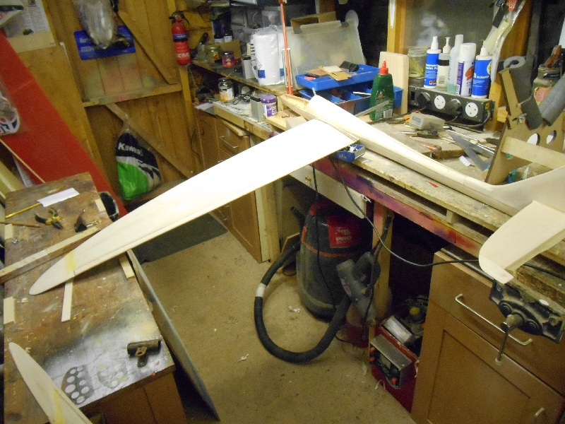
The wing. I spent quite a lot of time wondering how to build the wing. At first sight it looks quite straightforward, however, the curved LE and spars will generate lots of strange stresses. This means that the wing need to be assembled and sheeted while still pinned to the building board.

Before I start though, I need a full set of wing ribs. These were supplied by LaserCraft Services for a reasonable fee, cut from DXF files that I supplied


The only straight edge that I can work from is the hinge line for the ailerons or just in front of it.

To make sure that it stayed straight, a wooden straight edge was screwed to the building board and  the wing was assembled from that point.

So with the position of the false TE established, lines were drawn representing the rib positions.


A 1.5mm spruce false TE was cut and the ribs glued into place pushing back against the false TE. This was aligned to the upper edge of the ribs like this


Assemble the wing as you normally would


Note the false LE held in place by suitable weights and curving back as the ribs are fitted. It took a couple of sessions to get them all in place


The spar is laminated from 4 of 3mm square spruce strips at the root, tapering to 2 strips at the tip. A slight change from the plan. I originally intended to taper each spar backward - in the end, I used a stepped taper to get the correct fit, adjusting the spar slot in the rib until I get a nice snug fit.


This was the junction from 4 to 3 laminations with a slight taper on the outer spar


After the spar was fitted it looked like this, small 1.5mm gussets added at the rib/TE junction and then the wing was sheeted over - while the wing was still pinned down.


Left to dry/stabilise for 24 hours and then removed from the board and very quickly adding the lower spar and shear webs for the length of the panel


Don't forget to fit the servos. These are built in with  no hatches, if a servo fails it will be surgery to replace it.

The servo bearers are cut from 10mm square pine (B&Q) and simply glued to the upper sheet. The servos then are located in a lite-ply frame and glued and screwed into place. Align the arms before you proceed, there is no easy return path if you this wrong.

The wing joining tube is fitted and thoroughly glued into place.  The tube is glued against the webs - this makes a nice load transition from the aluminium tube to the spruce spars. The end stop is a 3mm off-cut of the joining tube epoxied into place


Finally, a small hardwood ply plate to hold the wing retaining screws


Add the lower sheeting (after removing the building tabs) and when dry, trim back to the false LE

The real LE comprises of a balsa laminate capped with a spruce laminate


and held in place with bands while the glue dries


The wing tips are laminated from 2 x 3/16 sheet balsa with a 1/32 ply core and glued into place


and the joint reinforced with a strip of Nylon - well soaked in PVA


The process was then repeated for the other wing half..


Glass Slipper (4)

The fuselage close to completion


Getting the last few planks in was quite tricky, just lots of patience required.


The canopy was acquired from Vortex Vacforms - CN39 Glider canopy - and extensively cut down to size. I am really pleased how well it fits and importantly how the fuselage lines have been maintained. Rather better than I could have hoped for.


The fin and tailplane came next.

The fin is a thick sheet balsa outline with a support for the tailplane


All very straightforward and all using very soft/lightweight wood.

It was simply glued into place checking for vertical - using the joiner tube as a datum in this case.


The area between the fin and the rear fuselage is simply blocked in using light 12mm sheet balsa.

Finally, the tailplane was added - laminated from 2 sheets of 3/16" balsa to get the desired thickness


Extensively carved, planed and sanded before it gets glued into place

Now with the rear block carved and sanded, it's hopefully getting its elegance back again


The tailplane is sandwiched between 2 x 12mm blocks and then sheeted in - not forgetting to fit the elevator and rudder push-rods first!


Like this


Which completes the fuselage assembly and we can start on the wing


Monday, 12 October 2015

Glass Slipper (3)

Come a long way since the last post:

 I completed planking the upper half of the shell and in the main I am very happy with it..

dscn1626.jpg

Lots of pins

dscn1627.jpg

Now that the rear planks have been trimmed, it looks somewhat better than the photo from a couple of days ago. Sanding at the stage involved just removing the 'edges' - it will be sanded down more thoroughly before it gets covered

dscn1637.jpg

And the front former (behind the canopy) after it has been trimmed and rough sanded. A little ragged on the LHS (of the pic) but acceptable

dscn1636.jpg

Now I can get it off the jig I can examine the inner surface. I am pleased with that - generally quite tidy. I took the fus (on the jig) down to our club night on Tuesday night (at the pub!). I was asked how I do the edge joins. I have done quite a bit of planking in the past. Obviously, when working around a curve, you need to bevel the edges to the planks to fit against each other. I think that the mistake is try and bevel both edges. Use a stripper to cut parallel strips - on this the main planks are 1/4 x 1/8 - cut with a stripper. I then place the plank vertical and trim a bevel using a razor plane. All done by eye - after a while it gets easy to judge the correct angle to hold the plane. The other side is left square. If you try and bevel both edges, you will simply end up chasing yourself round in circles. I have also stopped trying to cut tapered planks for the same reason. Just taper the edges where you need to fit them. It all gets covered up in the end so no-one will notice

This morning - after another bad nights sleeps and hence early start in the workshop, I removed the fuselage from the jig. Now in hindsight, it would have been much more sensible to have done the bottom first - there is more of it, however, by removing the middle jig supports, I have got it in the jig, cut the lower slot for the lower backbone and fitted it - this one is laminated from 2 off 1/8 sq spruce

Now being left to dry..
dscn1635.jpg

Planking has started on the lower fuselage, its quite tricky around the bend by the fin post but apart from that is mainly more of the same..

dscn1651.jpg

One thing I nearly forgot to do was fit the pushrod tubes for the rudder and elevator. It would have been very entertaining trying to fit them after the planking had finished

dscn1652.jpg

At the rear

dscn1653.jpg

and at the front..

Note both these photos are actually upside down 0 hope they don't upset your sensibilities and/or OCD

I have progressing the planking slowly

dscn1794.jpg

Just working down one side, adding one plank at a time and letting it dry. The pins are pushed through from one plank to the next making sure the line of the fuselage is maintained

dscn1803.jpg

A couple of days later.. This is as far as I can go. I need to get the other side this far - the next big job will be to fit the wing joining tube which sits in this slot


dscn1804.jpg

which will be opened up at both sides when it is fully supported by the planks.
Also need to add the rudder push rod

One area that I am bothered about, I don't think the fin is large enough and may redraw with the fin about 50mm taller. Not a show stopper at the moment though

Getting very near the end.

dscn1826.jpg

The idea is to get the wing joiner tube fitted, so plank down until you get to the slot in F4

dscn1827.jpg

Carefully remove the edge pieces with a Razor saw.. The former should be self supporting now.

dscn1830.jpg

Cut a length of the phenolic tube about 30mm too long and adjust the gap for a snug fit with the tube centrally between the upper and lower former halves

dscn1831.jpg

When happy, liberally apply a large dollop of slow setting epoxy.
Use the full length of the joining tube, centralised cross the fuselage and then triangulate to the fin post, ensuring that the distance is the same for both halves.

dscn1832.jpg

Then leave it to harden. Tomorrow evening, I'll carefully remove the joiner, then complete the planking. There are two thick (10mm) balsa end ribs capped with 1/16" ply that will provide the structural strength to the wing to fuselage junction

Fin and Tailplane next