Showing posts with label DHC-1 Chipmunk. Show all posts

Monday, 9 January 2017

DHC-1 Chipmunk - wing

After about a 18 month break, I have restarted work on the Chipmunk. The Fuselage has been parked for the time being and I have started work on the wings. Nothing too challenging at the moment, it is simply a case or reigniting my enthusiasm, getting a bit of progress and hopefully, I'll now see this through to completion.

As before, it will have to fit in with whatever else is happening in the Shed, but now I have got the irritating bits of the design out of my system (it's scale accuracy), I feel much happier and I'll now try and get this completed and with a moderate amount of scale detail. Like all large projects and eating elephants, its best to approach the task, one bite at a time.


The parts kit is almost complete (centre rib and 2 1/16 ply brace/doubler ribs not present - but that's not a problem) although the balsa wing rib wood is rather hard and prone to splitting. Still quite usable but I am not sure how it will survive a hard arrival.


Lots of clamps used to make sure the joints are nice and tight. The number of braces in the centre are in my opinion rather excessive but that is what we are stuck with. The wing certainly wont fold in flight. It was actually far more difficult to get the two panels to align correctly surprisingly. It took me 3 attempts to get it to where I am happy with it.


 Progress so far has been slow but the upper wing sheeting has been added. I can how start work on the aileron push-rods and the undercarriage. A bit of belt and braces while work progresses on the overly delicate Hornet Moth


I was never happy with the original method of retaining the torsion bar undercarriage legs which used tinplate straps binding the legs and then screwed to a hardwood block. The centre section is so over engineered - this looks like a potential weak point.

My approach has been to implement much larger beech blocks and cut a deep channel. Aluminium plate saddle clamps will hold the leg in place without risking damaging the wing skins  which sit below the torsion bar.


The anti twist stop will use a metal saddle clamp - bolted through the wing ribs


 Hobby King Oleo legs grafted onto the end of the torque rods. These are designed to be clamped. Its quite an easy task to drill out to 4mm to fit (interference) with the 8swg (4.1mm) diameter rod.

M3 hole drilled and tapped all the way through and cap head screws used to clamp the legs in place. A small flat will be ground on the legs to prevent them twisting


The sprint tension is too tight. The spring needs to be reduced in tension so that the leg compresses by about 6mm with (guessing) about 1.5kg load on them. I don't want to soften the spring, simply reduce the preload - the easiest approach is to incrementally reduce the spring length.

Monday, 18 May 2015

Dennis Bryant DHC-1 Chipmunk - Back end

This is my contribution to the RCM&E Mass Build for the Dennis Bryant Chipmunk. Built from the Traplet plan and part kit from about 40 years ago, the plan isn't quite as true to scale as I would have liked.

My build blog is here, but I thought I would put an occasional posting here as well..

This past weekend, I have been working on the tailplane and Rudder. Danny Fenton - a true scale master - has been guiding us through some of the steps needed to produce a realistic looking aeroplane. This is my first attempt at producing anything scale like.

Because all the linkages are hidden, assembly is really quite complex, so a couple of shots to show where I am.


The two linkages - upper rudder, lower elevator are buried in the fuselage under the tailplane and fin
The clevis connects to the tiller arm for the tailwheel, I need to attach the rudder tiller to the same rod.


Broadly, I have used a brass terminal screw block to clamp the rudder tiller. This has a short brass plate with a hole drilled in it The tube supports the axle and arm that drops into a hidden slot in the rudder. The pin protrudes down through the plate and has a soldered washer to retain it.


The tube is now supported by a small strip of lite ply. One problem is that the arms rocks very slightly as the tiller moves in an arc as it is turned from left to right. It moves about 0.5 mm. This is because the tiller lengths for the tailwheel and the rudder are slightly different. However, as you can see, the axle is a sloppy fit in the tube. I am really hoping that I can get away with it...


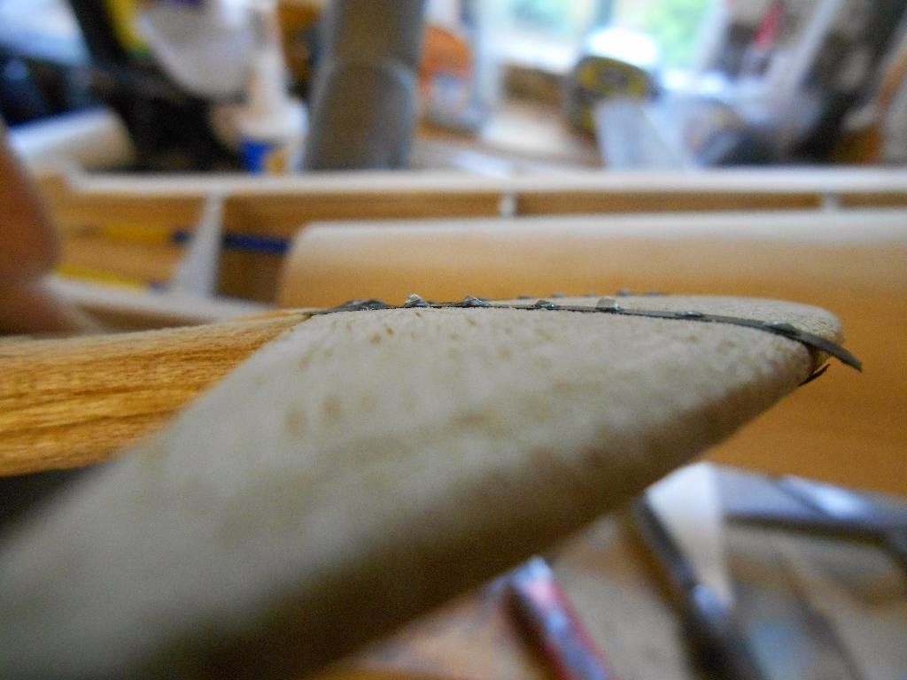
Now, following Danny's instructions, its time to add some rivets. I have added a couple of strips of vinyl tape to simulate a joint in the metal sub structure and then using small drops of PVA applied with a syringe, I have added a few 'rivets'.


The riveter is a cheap syringe with a little glue and lots of air. Danny uses a little dispending bottle, but my thought was that once I get the pressure right to get a slow but constant flow rate, it should be simple to quickly move from dot to dot adding the rivets. It seemed to work OK.


You can see from this shot they just stand proud..


 When done and allowed to harden ( for a good coupe of hours). the rudder was covered in White Solartex carefully avoiding the rivets as they would flatten under the heat. (in fact I lost 2 in the process)


The next task is to weigh up what order to assemble the rear components, this is far more complex that it looks. I also have to add a carved tailpiece to finish off the rear fuselage. This will totally embed the elevator linkage. However, I cant do any of that until the tailplane and fin detail has been added, so rib tapes and stitching next


This is going to be a long slow build..