English Translation/Interpretation for Class F3-RES thermal-gliders (Rudder, Elevator, spoilers)
1. General Provisionsa) “F3-RES” is a competitive class for radio-controlled gliders with a maximum of two (2) meter wingspan constructed predominantly of wood. Control is via elevator, rudder and spoiler. If used, spoiler(s) must be on the wing upper surface at least 5 cm ahead of the trailing edge. The spoiler(s) can be controlled with either one or two servos. Launches are to be done with a hi-start (see Section 6).
b) Definition of a remote-controlled glider: A model aircraft which is not provided with a drive device and whose sustained flight depends entirely on aerodynamic forces acting on its immovable surfaces. Models must be remotely controlled by the competitor on the ground.
c) In competition at least four (4) qualifying rounds shall be flown. For each qualifying round, participants shall be divided into flight groups. The results of each flight group shall be normalised to arrive at comparable scores between the flight groups. The highest score within each flight group will be assigned 1000 points and the remaining scores within that group shall be proportional to each participant’s raw flight score relative to the best raw flight score within that group. The group size in the “Fly-Off” shall be the same as the group size in the preliminary rounds. Participants flying with the highest total normalised scores from the Preliminary Round will compete in a “fly-off” (minimum 2 rounds) to determine the final classification.
d) The competitor may use a maximum of two competing models. A model may be replaced within a round only when the competitor’s prior launched model is returned to a point within a radius of 15 meters of the assigned Landing Point.
e) The participant may use up to three (3) assistants. These are to assist him in launching and retrieving the model, informing him of weather conditions and flight time and to manage the hi-start. At least one helper shall constantly ensure that the pilot’s assigned hi-start does not interfere with anyone else’s assigned hi-start. This requires that his pilot’s hi-start be immediately returned to its assigned position. In crosswind conditions the Contest Director may determine that the contestant who is farthest downwind begin with the start so that hi-starts do not interfere with each other during launching.
f) The organiser should have official scorekeeper / timekeeper available. If this is not the case, the pilot’s helper will keep time, and the organiser will regularly sample the flight times. Deviations of more than three (3) Seconds in favour of the participant shall lead to a zero score flight.
g) The landing points shall always taken by an official scorekeeper.
2. Model
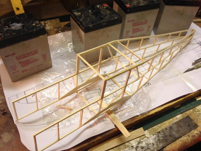
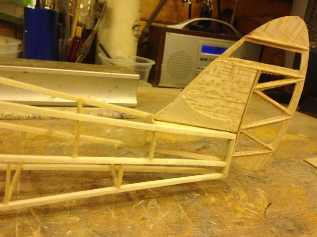
2.1. A model normally consists of wings, fuselage and tail. Flying wing models that do not have a fuselage and rudder or vertical stabiliser, or none of these components are also allowed if they have a total of only two (2) control surfaces. Each of these control surfaces must be actuated by only one servo. Otherwise, the building codes for a conventional model described herein apply. The model shall be fabricated primarily from wood. This means:
- For the wings, GRP/CFRP/Kevlar tubes or shapes may only be used for spars, wing leading edge and joiners.
- The tail boom for the tail unit may consist of a GRP/CFRP/Kevlar tube or shapes. The composite tube or shape may not extend forward of the middle of the root chord of the wing.
- The wood parts of the fuselage may be reinforced on their surface with GRP/CFRP/Kevlar.
- Control rods are exempted from the CFK/GFK constraint.
2.2. The following Are Not allowed:
- An all-GRP/CFRP/Kevlar or other plastic fuselage or fuselage pod
- GRP/CRP/Kevlar monocoque construction wing or tail leading edge, also no GRP/CRP/Kevlar DBox
- A stabiliser or wing made of GRP/CFRP/Kevlar foam planked or other plastic construction.
- Fixed and retractable devices for braking the model on Landing on the ground (e.g. bolts, serrated protruding devices, etc.). Nothing may protrude from the bottom of the fuselage other than up to two Towhooks (each a maximum of 5 mm wide x 15 mm high, seen from the front). The Towhook may be adjustable, but not by remote control.
- External ballast.
- Any telemetry with the exception of radio signal strength, receiver temperature and battery voltage.
- Use of telecommunication systems on the airfield by competitor and their helpers (radios and phones included).
3. Contest Field Layout
- The competition must take place on a terrain that is flat that provides the smallest possible chance slope or wave soaring.
- The flying site should have a designated Starting Line. The Starting Line is perpendicular to Wind direction and has marked Starting Spots for each competitor that are at least eight (8) meters apart. The “Starting Line” and stakes fastening the hi-starts to the ground of shall be parallel lines approximately 145 meters apart (possible Exception see item 6). The attachment points for hi-starts have the same spacing as the Starting Spots.
- Landing Spots should be at least eight meters apart and should be at least 10 meters downwind from the Starting Spots.
- The Landing Spots and the Starting Spots shall always be clearly marked. The distance from the fuselage nose to the Landing Spot shall be used to determine the landing score.
- The Contest Director shall determine the landing boundaries. Landing outside the boundary shall result in a zero score for that flight.
4. Competition Flights
- The competitor is entitled to at least four (4) official flights.
- The competitor is entitled to an unlimited number of attempts during a Flight Window.
- An official attempt begins when the model leaves the hand of the competitor or his helper under the tension of the hi-start.
- The Flight Window is nine (9) minutes long.
- A normal Flight Task is six (6) minutes long unless modified in accordance with 6(d).
- Timing for any Flight Task begins when the model separates from the Hi-start. It ends at the EARLIER of the time the model comes to rest for its last launch during any particular Flight Window OR at the end of the Flight Window. No time shall be measured AFTER the end of the Flight Window.
- In the case of several attempts, the result of the last flight is the official result.
- The Contest Director has the right to interrupt the competition and reset the Launch Line when the wind direction deviates.. He can cancel or suspend the competition if wind of more than six (6) meters / second (13.4 mph) measured two (2) meters above the ground at the Launch Line and prevailing for a period of at least one (1) minute.
5. Re-flights
The competitor is entitled to a re-flight when:
The competitor is entitled to a re-flight when:
- His model collides with another flying or launching model.
- He is prevented from launching or relaunching as a result of his hi-start being fouled by another hi-start.
- When his flight is hindered or aborted by an event beyond his control.
- To claim a re-flight in accordance with the reasons set out above the competitor must land as soon as possible. If the competitor continues to fly it is assumed that he waived his right to a re-flight.
6. Launching
- Identical Hi-starts shall be furnished and set up by the organiser.
- Hi-starts shall consist of a 15 ± 0.5 meter rubber tubing and 100 meters nylon line with a minimum diameter of 0.7 mm with a flag attached.
- When extended to a length of 45 meters, the rubber tube shall not exceed a pull of 4 kilograms. The deviation between the rubber tubes shall not exceed 0.4 kilograms.
- At airfields that will not accommodate a total hi-start space of 145 meters, the Contest Director may shorten the nylon line and shorten the corresponding flight time. Such changes should be included in the Competition Notice.
- Competitors may not extend their respective Hi-starts past their assigned Starting Spots.
7. Landing
- Before each flight each competitor will be assigned a Landing Spot that corresponds to his assigned Starting Spot. It shall be the responsibility of the competitor to use the correct assigned Landing Spot.
- During the landing process only the pilot and his assistant are allowed in within 10 meters of the Landing Spot. Any other helpers and timekeepers shall remain at their assigned Starting Spot.
- After any landing, the pilot or helper may retrieve his models during the task Time Window if this retrieval does not interfere with other planes and pilots flying in the group. A model thus retrieved may be relaunched during the Task Window. No landing score may be recorded for a model that has been touched before scoring the landing.
- No landing score will be allowed for a model whose tail does not come to a rest on the ground.
8. Scoring Flight Performance and Landings
8.1 Scoring of flight performance:
8.1 Scoring of flight performance:
- A nine (9) minute Task Window starts with a sound signal by the Contest Director.
- The flight time starts when the model disconnects from the Hi-start.
- In the event of subsequent launches during a Task Window the Flight Time will start when the model disconnects from the Hi-start for its last launch during the Task Window.
- The Flight Task Time is six (6) minutes to be completed entirely within the nine (9) minute Task Window. The flight time is recorded in seconds without rounding. Two (2) points will be awarded every second flight time.
- The Flight Time ends at the earlier of:
- When the model stops moving after its final launch during the Task Window or:
- At the end of the Task Window (Nine (9) minutes after the start of the Task Window. The Contest Director will make a sound signal designating the end of the Task Window.
8.2 Scoring of the landing:
a) The landing score will be determined by the distance between the nosecone of the plane (Or the most forward point on the centre line of the plane) and the designated Landing Spot with the plane at its final resting spot. Depending on the distance the following points are awarded:
b) Zero points for landing the participant if:
a) The landing score will be determined by the distance between the nosecone of the plane (Or the most forward point on the centre line of the plane) and the designated Landing Spot with the plane at its final resting spot. Depending on the distance the following points are awarded:
| Distance in m | Points | Distance in m | Points | Distance in m | Points |
| 0.20 | 100 | 1.80 | 92 | 9.00 | 60 |
| 0.40 | 99 | 2.00 | 91 | 10,00 | 55 |
| 0.60 | 98 | 3.00 | 90 | 11,00 | 50 |
| 0.80 | 97 | 4.00 | 85 | 12,00 | 45 |
| 1.00 | 96 | 5.00 | 80 | 13,00 | 40 |
| 1.20 | 95 | 6:00 | 75 | 14,00 | 35 |
| 1.40 | 94 | 7:00 | 70 | 15,00 | 30 |
| 1.60 | 93 | 8.00 | 65 | > 15.00 | 0 |
b) Zero points for landing the participant if:
- The plane’s tail does not come to a rest on the ground.
- The model sheds any parts.
- The model is not airworthy after the landing.
- The model is still flying after the end of the Task Window.
- The pilot or his helper model the touches,
- The model is moved by the pilot or helper before a landing measurement is made.
- The model comes to rest outside a Landing Boundary specified by the Contest Director.
- The model has not landed within 30 seconds of the end of the Task Window.
- Each competitor’s Raw Score in a round will be the sum of the Flight plus the appropriate Landing Points.
- Within each Flight Group, each competitor’s Raw Score will be normalised by multiplying the proportion of his score for that round to the highest Raw Score within his group in that round multiplied by 1000.
- Each competitor’s Raw Qualifying Score will be the sum of his Normalised Total Scores for each of the Qualifying Rounds. Each competitor’s Normalised Total score in the Qualifying Round will be restated as a percentage of the best Normalise score for the Qualifying Round. For example, if the best Normalised Total Score for the Qualifying Round is 3995 points and another competitor has a score of 3500 points, the other competitor’s score for the Qualifying Round would be: 3500/3995x100 = 87.6. Other Qualifying Round Scores will be computed the same way.
- The highest scoring competitors in the Qualifying Round equal to number of competitors the largest group flown will advance to the Flyoffs.
- The Flyoffs will consist of at least 2 Rounds flown the same way as the Qualifying Rounds, but only by the pilots determined in 8.4.b above.
The winner of the flyoff will receive 3 bonus percentage points in addition to his score for the Qualifying Round. Second place in the flyoff will receive 2 bonus percentage points, third place, 1.5 bonus percentage points, fourth place, 1 bonus percentage point and fifth place, 0.5 bonus percentage points. All other competitors will receive the percentage points earned in the Qualifying Round.
10.0 Advice for Contest Notice
Each participant is flying at your own risk and liability, has a valid insurance coverage and/or BMFA or equivalent membership. Participants agree to make no claims against the organiser.
The Contest Notice will state any expected modifications in the total length of the hi-start and/or Task Time because of space limitations.


.jpg)


